Hello BIMfans,
Welcome to ‘Is It Smart’, a blog series where I have a look at the smart technology installed within Ty Crempog as I explore the power of BIM level 2, PropTech, and the Internet of Things(IOT). This week, I take a look at my Amazon Dash Buttons.
What is it?
The Amazon Dash Button is a Wi-Fi enabled device, linked to specific products on Amazon. When you are starting to run low of a product, you simply press the button and an order will be placed and delivered using the details you have provided.
How Does it Work?
Using an Amazon account, you register the Amazon Dash Button as a device (like you would a Kindle). Once the device is registered, you are able to select a product from the shortlist Amazon supports for your branded button (ie I can’t get myAndrex Buttonto deliver Velvet or Cushelle).
Once all of this has been completed, pressing the button sends a command over WI-FI to place an order for that product; it’s as simple as that. The button also has a fail-safe that stops someone from pressing it multiple times by as default only allowing a single active order.
How Did I Model it?
My Amazon Dash Button can be downloaded from here.
Following the voting, the majority of people thought that it should be a Communication Appliance. However, I have overruled this verdict and used SwitchingDevice_MomentarySwitch (Sorry!). I did this as my Amazon Dash Buttons have no ‘position’ and simply trigger an action to occur; making them switches.
Similar to my Nest ThermostatI used a face based generic model to create my object, but this time I have modelled the object as a solid oval. Due to the low level of graphical detail used the object file is only around 296KB. The file was named following the BS8541-1naming convention to:
Amazon_SwitchingDevice_DashButton
Using the requirements set out within my Data Requirements, I populated this object with the data needed to manage my Amazon Dash Buttons. Capturing information such as: Installation data, serial number, replacement cost, and warranty information.
Is it Smart?
The Amazon Dash Button, unfortunately, doesn’t really tick the right boxes to be considered smart.
Data in: Without any sensors, the data input method on the Amazon Dash Buttonis the button itself which means that the ONLY way to active it is by physically pressing the button. Also annoyingly, the buttons settings can only be edited through the mobile app, and these settings are rather limited. For example, there is no way to rename my buttons despite being able to name other devices on my account.
Why, why can’t I rename these buttons?
Data out: There is also little data available from the device. Aside from the default order history held on an Amazon account, no other information is available apart from a confirmation email received after the button is pressed.
Connectivity: Due to the proprietary nature of the service, it is no surprise that it offers little connectivity. These buttons are basically physical Do Buttons, but without any connectivity to other applications. Of course, that hasn’t stopped some people from thinking of Amazon Dash Button Hacks.
The Potential
Think of all the fun it would be to trigger amazon deliveries if they spoke to each other…
Currently, this use of these buttons is very limited. If Amazon had opened up the button’s so that it could connect with IFTTT, then it would blow their potential wide open allowing for activation through triggers as well as physical presses. This would also have the benefit of allowing recipes to store a log of when the buttons where pressed, which could then be used for settings future budgets as there would be a record of how often the buttons are pressed (or triggered).
The Verdict
Is it Smart? The answer is no, with an IQ of only 70.
The Amazon Dash Buttons sounded pretty interesting when they were first released, however, after fitting a couple into my home I am disappointed at how little information I get out and put into them. Compared to other smart home products, it seems odd how isolated the Amazon Dash Buttons are especially when you consider how connected something like Amazon Echo is. The biggest disappointment is how I am forced to select only a few products from a pick-list. This meant that only bulk orders could be selected which came as quite a surprise when they arrived.
45 loo rolls are more than enough! No-one press the button for another six months!
And there you have it, This week my Amazon Dash Buttons didn’t prove very smart. Tune in next time when I consider my Google Home and ask one simple question; Is It Smart?
Hello BIMfans,
After looking into the follies of language in our cold digital world, I wanted to revisit my BIM Execution Plan (BEP). The reason for this is because my BIM Execution Plan is the guidebook being used to create my information model; the clearer it is, the better quality the information contained within the information model will be. So, it is time for an upgrade.
Looking over what I have done so far, there is a lot missing from my current BIM Execution Plan. It’s for for it to mushroom into a much more usable document.
Going through my BIM Execution Plan now that I have started to create content, I have noticed a few items and headings that I should have included which can be summarised as:
Revision and Status Code Details;
Classification;
Object Naming; and
Attribute Data Conventions
Now the great thing about a BIM Execution Plan is that it is a Live & Evolving project document, meaning that there is no issue with revisions to the document so long as the impact of those changes have been fully considered.
Revision and Status Code Details:
While I have previously specified compliance to BS1192, in reality that isn’t good enough, as it is possible to misinterpret the use of these codes. So I have included the following diagram as an aid:
Instead of focusing on where the document sits in the Common Data Environment, I have instead focused on the level of approval/authorization the file has been given.
For example, many believe (as I did not so long ago) that if they were issuing information to an estimator that they would use the status code D1; this is incorrect. As you can see from BS1192, table 5 ‘suitable for costing’ relates to unapproved information. The intention is that this code allows information to be given to someone (like as a manufacturer) to get a unit rate cost to then be used as part of generating the cost estimate.
To enforce this I have included the following clause within my BIM Execution Plan:
D codes shall be exclusively for unapproved information exchanged to aid in at-risk preparatory work. Information with a D code status shall not be referenced to generate any deliverables.
In summary, if you see a D code, think ‘D, do not use’. As you cannot rely on the information within, as it hasn’t necessarily been approved by the authors task team.
Classification:
In order to ensure a simple application of class, objects will need be classified by a single classification code. This means that while some might have a Swiss army knife of functions, they will be classified by their primary function. For example, my phone is a computer, camera, and sensor (and as it is a Samsung, a potential tool for arson) but is marketed as a phone; so my Nest Thermostat will be classified as a thermostat* and nothing more.
To enforce this I have modified by BIM Execution Plan to include the following clause under 5.8, and amended Appendix E to suit:
Only a single classification code shall be included on each object which describes its the primary function. Classification shall be included in the Attribute ClassificationForObjects included within Appendix E.
Typically ClassificationCode is used as default, but as ClasssificationForOjbects is included within IfcClassification I have opted to use this instead.
Note: There is no thermostat in Uniclass 2015, so I have had to default to Mechanical Services Control Product.
Object Naming:
We have discussed how to name objects in previous posts, so I will not repeat myself here. However, as I mentioned last week it isn’t always as simple as complying to the standards; for one there is no guidance on Type Naming.
To enforce this I have modified by BIM Execution Plan to include the following new Heading and clauses under 5.4 Object Naming:
To satisfy EIR, section 3.5 all objects produced will be named in accordance with BS8541-1.
Specified below are the permitted values for each field.
Source
Type
SubType
Author, Manufacturer
See Ifc[Type]
See …TypeEnum See product name
All objects types shall also be named following the following convention: […TypeEnum]Type[Number] e.g DoorType01.
By using the objects allowed enumerated values I get a consistent a human readable set of Object Types
Attribute Data Conventions:
Finally to control the application of consistent attribute data I have come up with the following convention which has been included within my BIM Execution Plan:
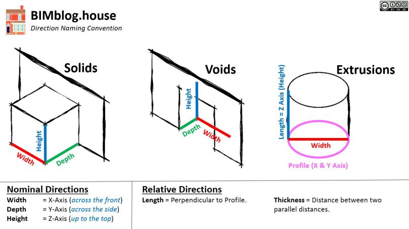
I now have a consistent (and likely controversial) way to naming my direction attributes.
For consistency I will be using the following convention:
Width = X-Axis (across the front) Depth = Y-Axis (across the side) Height = Z-Axis (up to the top)
For a Boiler it is rather simple. It has a Height, Width, and Depth. As it has no profile it is given no Length, leaving Height and Width to appear on the type worksheet, and Depth to appear on the attribute Worksheet. While this may seem a little messy, the benefit will be realised once the information is exported out of COBie and into a data management system (who knows what you would measure if someone asked how ‘long’ your boiler is).
For a Door this can applied in a fairly straight forward manner. My doors have Height and Width, but depth is controlled by the host so it isn’t required (as it is instance driven); so I only need to record Height & Width. Once again, as it has no profile it is given no Length.
My Kitchen worktop on the other hand is a little more complex.
As you see the profile used is the side of the worktop (Y-Axis), meaning that the length is perpendicular (X-Axis).
By modelling my kitchen worktop the way I have the profile has a Height of 38mm, a Depth of 625mm, and a variable Width (Width=Length). This means Width isn’t required (as it is instance driven), leaving Height and Length and to appear on the type worksheet, and Depth to appear on the attribute worksheet.
And there you have it, by spending a little longer sorting out my BIM Execution Plan, I have a much tighter set of Standards, Methods, and Procedures to following which will resulted in a better data set now I am at the final stretch in completing my information models…
Hello BIMfans,
After giving my attic some attic-tion (sorry, again) I wanted to talk to you about an issue I am having. This issue isn’t directly related to production of my graphical models or information, but it is having a BIG impact on both of these; it’s language.
As a man fluent in three languages (Welsh, English, and Sarcasm) I often consider the failings in how we communicate.
Our language(s) are incredibly analogue, making it difficult to fit what we say into our logical, cold, and uncompromising digital world; with English is particularly difficult. As a quilt of a Language, English has inherited many inconsistencies such as: Strange pronunciations (Slaughter is Laughter with an S at the front), and inconsistent terms etymology (Pig is German, while Pork is French). Languages like Welsh on the other-hand are phonetic, and use consistent terms (Moch = Pigs, Cig Mochyn = Pig Meat).
Most of you (at least according to the blog’s analytics) will be glad to hear that this ins’t a post about the superiority of the Welsh Language, but it is instead a post about the follies of trying to digitise information using the analogue method of communicating and structuring information known as language.
Classification
Our world isn’t black and white (Zebra’s & LinkedIn Profile pictures being the exception), so it is easy to misclassify (or overclassify) objects. From the Tree of Life to Uniclass 2015 it is not an easy job to provide order to this chaos; leading to difficulties when trying to classify.
“What do you mean mammals don’t lay eggs?” Platty also finds classification a difficult concept.
I’ve written about my Nest Thermostat previously but I didn’t mention its classification. My Thermostat, being a clever tool, functions as many things and therefore could be classed under Uniclass 2015 as a: Pr_70_70_47_21: Daylight Sensor, Pr_75_50_76_73: Room Temperature Sensor,Pr_80_51_85_21: Data Logger, Pr_40_30_25_23: Display Screenand many others. Its primarily function however is as a Thermostat, with the closest classification I can find being Pr_75_50: Mechanical Services Control Product.
This means that while everyone on a project might be using a single classification system, there is to guarantee that they will use it consistently.
Would everyone classify my Nest Thermostat as Pr_75_50: Mechanical Services Control Product?
Naming
Just like classification, we are also terrible when it comes to naming. For example, due to the fact that radiators emit 80% of their heat as convection, and 20% of the week as radiation; radiators are actually convectors.
In addition: Models aren’t federated, federation is for federal unions; they are really integrated models; Gargoyle have water spouts; without spouts they are grotesques; and BIM barely has any acronyms. Acronyms are spoken as words, meaning that terms like EIR, DRM, TIDP, MIDP, IFC, IDM, bSDD, and BCF are actually Initialisms. +10 Pedant Points
To show how complex naming can be, last week on Twitter I asked how to name my Amazon Dash Buttons (Wi-Fi enabled buttons for ordering products off Amazon), and the results were inconclusive.
When is a ContactSensor not a Switch? When it’s a CommunicationApplicance…
This means that while everyone on a project might be following the same Object Standard, and even using the IFC Schema to limit their choice of relevant Types and Sub-types, there is to guarantee that they will use them consistently.
Would everyone name my Amazon Dash Buttonsas CommunicationAppliances?Not even I would, as I’d use Switch_MomentarySwitch.
Distances:
In mathematics numbers have an order for numbers. We have:
Cardinal numbers, the principle set of numbers;
Ordinal numbers, used to provide a ranking; and
Nominal numbers, used to identify (not necessarily by rank).
The same can also be applied to Directionsfor both Cardinal or Ordinal, but what about Nominal? Well as nominal numbers are used to identify, then Top, Bottom, Front, Back, Left, & Right can be considered Nominal Directions; but how to measure these distances?
If I wanted you to measure the distance across the front of a cube, what are you measuring its length, width, breadth or depth? The answer will differ depending who you ask as there is no consistency on how we name these distances.
This isn’t a new topic, many have discussed it previously such as Practical BIM when considering Which Direction is Depth?, and more recently Keith Wilkinson is conducting a survey to gain a consensus on what to call these directions.
How would you identify these distances? Why not try Keith‘s survey, which can be accessed here.
In many commercially available authoring tools, you are able to name (and in my case misspell) these distances anything you like. So while we might instinctively know what to measure when asked how tall a door is, when we are asked how wide a cabinet is; there is plenty of room for varying interpretation.
This means while everyone might be using the same language, variation in how it is used can change the values recorded against attribute data such as Height, Width, Depth, & Length; all of which are required by COBie.
Would everyone call distance B width, and distance A depth on this cube? What about a more complex shape?
On this project I have specified Uniclass 2015, BS8541-1, COBie, & additional EIR attributes so I have a consistent method of classifying, naming, and attributing data. However, it is one thing to specify their use, and quite another to ensure that they are being used consistently and appropriately.
The only way to ensure that the application of this information correctly is to further qualify their use within my BIM Execution Plan, it looks like a revision is in order…
Hello BIMfans,
After considering the Type Trouble I have been having when looking at my doors, I decided put some more work into Architectural Model. This week I have tried to give my attic some attention, so it was time to get up the ladder and have another look.
If any of you reading know me, you’ll know that I’m no da Vinci; so I apologise in advance for the quality of the sketch below. To develop my Architectural model, I decided to first draw out a few of my key junctions, measure the relevant elements, and then produce my information model.
Model progression: Sketch of Junction (Left), Unedited callout of junction from graphical model (Centre), detailed callout (Right).
The reason I developed my graphical model this way was to limit the amount of overall modelling that I needed to do. I’ve discussed Level of Definition before as I am a firm believer of modelling as efficiently as possible. For example, to limit the amount of modelling I need to do for my roof I have set a number of informal ‘volumes’ within the roof itself using Revit’s built-in system family layering function:
Manageable spatial subdivision of a project, defined by the ‘project team’ as a subdivision of the overall project that allows more than one person to work on the project models simultaneously and consistent with the analysis and design process.
While formal volumes can acting as a tool for simultaneous working, I have also used informal volumes to limit the amount of modelling required. Each volume, as a subdivision of a project, is effectively a geometric space assigned for a particular system, element or array of components to be populated within. Typically, as the design develops these volumes can then be assigned to sub-consultants who would then populate them with their objects.
A volume strategy is no different than a 3D ‘Paint by Numbers’.
Therefore these informal volumes I have created for myself can be used in two ways.
As a substitution for objects. For example, it would be practically impossible to model each roof tile and batten, so instead volumes are used. This also applies to other elements such as Walls (who’d model every brick?); and
As a placeholder for objects. For example, my rafter volume was drawn initially as a substitution, but this week I have added them to my model. If objects are placed within their respective volumes, then a clash free model can be created as any clashes that may occur within this volume are ‘known’.
As you can see, my rafters and joists have been placed within their volumes.
Finally, to sort my attic I also had to have a look at my party wall. Now very interestingly my party wall isn’t fully constructed (apparently this was fairly common when terraces like mine were constructed). This along with its annoyingcomplex interesting profile has allowed me to generate some unique geometry to complete my attic.
While I admit that the exact profile of the party wall is an estimate, it provides a much more accurate account of the existing physical conditions compared to earlier iterations of my Architectural model, accessible here through A360.
By completing both of these elements of work I have also been able to generate another Stereo Panorama, with my partially constructed party wall providing a convenient light source when it was rendered (thank you Victorian builders?).
And there you have it, by exercising some attic-tion to detail (sorry!) I have now captured the geometry of my attic, as well as some useful elements that will aid future posts such as the amount of loft insulation and my half constructed party wall. Now that my Attic is sorted, I wonder which other parts of my Architectural model also need to be optimised before I can consider it complete…
Hello BIMfans,
Welcome to ‘Is It Smart?‘, a blog series where I have a look at the smart technology within installed Ty Crempogas I explore the power of BIM Level 2 and the Internet of Things (IoT). This week, I take a look at my Nest Thermostat.
What is it?
The Nest Thermostat is an electronic, programmable, Wi-Fi enabled thermostat that learns from real-time use to optimize heating. I currently have it installed in 002: Living Room as it is the most frequently occupied room in my home. It has a series of built-in sensors that measure temperature as well humidity, motion, and ambient light.
How Does it Work?
The UI is incredibly simple to use. Also, you can customize the location, so my Nest is now in 002: Living Room to match my information model
When installed, the Nest Thermostat is connected over Wi-Fi to the boiler via an additional device called Heat Link which bypasses the boiler controls.
Quite simply, the big number in the middle is the programmed temperature (19) and the gauge shows the current temperature (21). When the current temperature drops below the programmed temperature the heat link is activated; telling the boiler to run on full. Once the programmed temperature is reached, a signal is sent to the heat link to deactivate the boiler and the cycle repeats indefinitely.
How Did I Model it?
My Nest Thermostat family can be downloaded from here.
Under the Industry Foundation Class (IFC) Schema, a thermostat isn’t included (it doesn’t appear untilIFC4) so I have had to resort to IfcSensorType. So, using a face based generic model I created a hollow cylinder and two inserts to represent the thermostat. Due to the low level of graphical detail used the object file is only around 316KB. The file was named following the BS8541-1 naming convention to:
Nest_Sensor_LearningThermostat
Note: Strangely, IfcUnitaryControlElement is included within BS8541-1, but not in the IFC2x3TC1 schema. So for consistency, I haven’t used it.
Using the requirements set out within my Data Requirements, I populated this object with the data needed to manage my thermostat. Capturing information such as: Installation information, bar code, serial number, replacement cost and warranty information. NOTE, my thermostat is one of the few items I manage within its warranty period.
When used in collaboration with my IFC Export mapping text file, my thermostat is populating all of the relevant COBie fields I require; fantastic.
Is it Smart?
The Nest Thermostat ticks many of the right boxes to be considered smart.
Data In: With a number of sensors, a Wi-Fi connection, and both physical and digital interfaces methods there is a wealth of ways that it can collect data. As a result, the thermostat learns about the space, proving an estimated amount of time needed to take effect based on past data. In addition, Nest stores a heating programme for your home and maintains an activity log.
As you can see, the fiancee decided to put the heating on before bed last week which I only discovered when writing this blog post. Cold!? It’s September!
Data Out: Each month, Nest also provides owners with a report detailing how long the heating has been on as well as an update about the performance of my devices. If you want more sophisticated data out of your nest, the API can be accessed here.
2 hours of heating in June!? I wonder who did that…
Connectivity: The ease that the Nest Thermostat can connect to other devices is a real strength. Other products included within the ‘Works with Nest‘ category are able to access information from the Nest Thermostat. For example, as a security feature, my Philips Hue bulbs will intermittently switch on/off in the evenings if my thermostat is set to ‘Away’. In addition, as discussed in a previous post, through the use of IFTTT my thermostat can trigger (and be triggered) by other events. Currently when my thermostat is set to ‘Home’, I receive a welcome home message in addition to any tweets from @TyCrempogwhen it is too hot or too cold.
As clever as this is, there is nothing more worrying then seeing this message on your Twitter feed when you are away on business and the fiancee is in work. #BlameTheRabbit?
The Potential
Imagine the data I could give my thermostat when my COBie files are full.
Currently, there is no method to automate the exchange of information to my Nest Thermostat from my information model; but this doesn’t have to be the case. For example, within my Architectural model, there is a lot of good information that the Nest Thermostatcould take advantage of including: Facility Name, Space Name, Area, & Volume and perhaps even external object thermal transmittance.
This kind of information could potentially improve the Nest Thermostat‘s ability to predict and control the temperature of my home if there was a way to import it.
The verdict
Is It Smart? The answer is Yes, with an Impressive IQ of 130!
Since we had planned to buy our first home, the Nest Thermostat had always been on my shopping list and may very well have been the first purchase I made. I’m glad to say it has not disappointed.
Since programming in a compromised heating schedule, I have barely had to touch the Thermostat control for the past 12 months. While fairly simple in function, the Nest Thermostathas a lot of data being considered in the background, coupled with an impressive list of connectable products and regular reporting, it was always going to do well.
And there you have it, This week my Nest Thermostat has proved to be quite smart. Tune in next time when I consider my Amazon Dash and ask one simple question; Is It Smart?
Hello BIMfans,
After looking at how I will be Bridging the Attribute Gap, I have now started to finish populating my graphical models to satisfy my graphical and information requirements. However, a practical problem has appeared which I wanted to share you with around type naming.
A while ago, I discussed good practice around 3D Modelling & Object Naming, this related to the file name (how you would find that file in a folder) using BS8541-1 to the point that I am able to use pretty effectively name all of the objects (thatRevitallows me to rename). What we didn’t discuss is type naming, now Rob Jackson of Bond Bryan talks about it much more detailed in his blog here, but put simply an object’s type name also needs thorough consideration. However, as I didn’t properly consider them a problem has been brought to my attention; let me explain.
When is an IfcDoor not a door? When it’s an IfcJar!
Shown above are the different door families in my home. Each family has a unique name and happen to only require a single type which I have named following Revit’s guidance for type naming through using a dimension-based type name. Meaning that the family and types names are as follows:
BBH_Door_FourPanel;
. 830x2035mm
BBH_Door_Stair;
. 600x1760mm
BBH_Door_Trapdoor;
. 680x680mm
BBH_Door_TwoPanel; and
. 830x2035mm
BBH_Door_SixPanel.
. 830x2560mm
Can you spot my problem yet? No, neither could I at first.
The way families & types work in Revit means that an object’s type isn’t necessarily unique. This isn’t a problem in Revit, but can be a problem when exported into other tools and systems, such as when I export into COBie.
Which 830x2035mm is the one I want?
Ideally an objects type should be unique and human readable so that it is clear which object is being referred to. To do so, I can see two solutions:
Family & Type
The term type can be a misleading one. In BS1192-4, type is defined as the named specification for components which means that using ‘Revit Speak’ both the family & type constitute the object’s type. This means that if I could export the object’s type as <<Family>>:<<Type>> I would have a unique reference for each type. However, while this isn’t supported by the IFC Exporter it is supported by the COBie Extension for Revit which solves the problem for COBie, but means that there isn’t a supported solution for any other exchange method, such as IFC.
A more practical solution then may be not to describe the size of the object but instead give it a name that is easier to understand. Both Revit’s guidanceand the definitions within the IFC Schema refer to what I call the ‘<<Type>>N’ method, for example using a type name such as DoorType01 to describe each object’s type. For a scheme like mine (without any design) this can be easily applied, but for a more iterative project an issues can occur if a Type becomes redundant during the development of the graphical model.
So let’s give it a go.
As you can see, I have replaced all of my dimension-based types with a type description based on the order you’d find them in my home.
This method doesn’t change how my doors are set up in my model but provides two advantages. The first is that when this information is exported into COBie there is no duplication which means that it is clear which type is which.
Instead of being unsure which 830x2035mm I need, I can instead just use DoorType04, easy.
There is another advantage too. If a dimension-based type name is used then there is a chance for error due to the manual input as well as the need to update the name each time a change to the object occurs. Using a name such as DoorType04 mitigates these potential issues.
And there we have it, by considering how I name my types, each type now has a unique reference that doesn’t duplicate other data and is less prone to error. This means that once I have replicated this throughout my model I will be well on my way to completing PLQ2.5!
Model Generation: 2.1 What existing information is available? 2.2 Is there sufficient information to produce a BEP? 2.3 What is the layout of the house? 2.4 What assets are contained within?
2.5 What asset information can be linked to the graphical model?
Now that I know how to resolve my types it’s time to explore my other attributes so that I can capture all my required metadata. But first I want to tell you about my year with Nest…
Hello BIMfans,
I have a special announcement I want to share with all of you.
Since staring this blog just over six months ago (if you want to read the reason why I started it, here is theprologue), I have published 27 posts and gotten over 3,400 unique visitors. I have been blown away by it’s popularity, so enthused by the support I am getting, I have decided to improve and expand the blog.
BIMblog.house, the blog Pokemon. Updated Monday’s this blog attempts humour through cult references and self-deprecation; it’s not very effective.
New Theme
You may have noticed that the blog has gotten a face-lift. Instead of the previous theme Franklin, I am now using Nucleare a free WordPress theme by CrestaProject. This theme is gorgeous, and gives the site the exact feel I am looking for.
New Menu
I have restructured the blog menu. Under the ‘About‘ section, there is a new page dedicated to Testimonials that I will be populating shortly (feel free to submit, wink wink). I addition I have the following new sections:
Engagement, dedicated to interactive content, first on the list are some stereo panoramaslike this one of myliving room, this heading will also include my published models,and I have a few more ideas currently brewing too;
Discussion, dedicated to future opinion posts with historic ones being transferred over too from other sites such as The Great British BIM Off from last year; and
Smart Homes, a new blog stream I am particularly excited about.
New Direction
Before Christmas I will have completed the blogs’s original purpose by having completed and documented the creation of an information model about my home capable of producing BIM Level 2 compliant deliverables. However, I feel that while I document some operational elements there is more value this blog can bring. As such, I will also starting posting ‘Smart Home‘ related blogs.
As you know, I already have a number of smart products in my home including:
In a few weeks I will have done a full 12 month cycle with my Nest Thermostat; from that moment I plan to post reviews of my existing smart products as well as others I will be acquiring. These won’t just be simple reviews, as I also plan to discuss how I have represented them in my information model, and what data I need to capture about each of them; showing the relationship between BIM, IoT, Smart Homes, and 3D Modelling.
Note: Please feel free to let me know of any products you think I should get for my home. A few of you have already tweeted me about Amazon Echo (I’m actually going to wait for Google Home), but if you have any other suggestions, I’d love to hear them. Or if you have a product you think i’ll be interested in, send me a tweet, wink wink.
So there we have it, my grand plans for the future. I hope you will continue to support
“One man’s dream to BIM & IoT his Smart home”
Because despite all of the incredible intelligence we put into our projects; in reality, There’s no BIM like home.
By doing this, I can clearly define the data gap that’ll allow me to complete my information model; surprisingly, I am a lot closer than I had thought.
By defining my data deficit, it’ll allow me to focus on building the right data to bridge this gap
Where best to store and manage the data?
Now it is worth pointing out that I have already put a lot of consideration into what attribute data I want to capture. I did so by defining my Model Purposes, which led to the definition of my Data Requirements. Which helped filter down the information I want to capture.
This process has helped keep my data muscular and compact, like corned beef.
This information will be stored in a number of locations. The files themselves will be held on my Google Drive while some information will also be transferred into Chimni. To exchange this information out of my information model into Chimni, COBie will be my method of choice.
Now through this process I am generating three kinds of container (files holding data): Graphical data (2D & 3D models), Non-graphical data (Schedules & COBie), and Documentation (Reports, & Drawings). When I need to amended this information however it will almost be exclusively through the graphical data. There are two main reasons for this:
Most of my non-graphical data & documentation are originated from my graphical model; and
Documentation are created in a locked format (such as PDF) making their management difficult, while non-graphical data are either used as reference (such as Schedules), or for the transfer of information between applications (COBie).
Note: There are many articles online that criticise COBie as a means to manage data; they have however misunderstood how COBie is meant to be used. COBie is the vehicle to transfer information either into a more user friendly format (everyone knows excel), or into another application where it can be managed effectively. While you COULD use COBie to manage your data, it is just as fit for purpose as a BMX is for competing the in the Tour de France.
I’m winning!
What’s Missing?
So what attribute data am I missing? Well, what attribute data did I ask for? Looking back at my Data Requirementsand what is written in my Employer’s Information Requirements (EIR) I asked for sufficient attribute data to comply with BS1192-4 (COBie), and a number of additional properties to suit my model purposes. So let’s see what we have already successfully managed to capture.
Note: I could have fixed a number of these issues before this weeks post, but I chose to highlight the current gap as opposed to present a ‘Blue Peter’ solution.
Contact
Nativity there isn’t sufficient support within Revit for ‘Contacts’. Therefore not much of information I require is being exchanged. Currently the following fields require attention:
Category: remains as ‘n/a’; Phone: remains as ‘n/a’; OrganizationCode: remains as ‘n/a’; and Street, PostalBox, Town, StateRegion, PostalCode, and Country: remains as ‘n/a’.
From a contact point of view I need to investigate the best way to manage this information either through a plug-in, or through an external database. – Score: 10/19 = 52%
Note: It is worth noting that the COBie extension for Revit is able to capture this contact information, but is not being used due to my desire to follow a more open approach.
Facility
By completing the ‘Project Information’ settings within Revit & the IFC exporter plug-in, the majority of information I require is being exchanged. Currently the following fields require attention:
SiteName: Cannot rename the Site system family in Revit to comply with BS8541-1; CurrencyUnit: remains as ‘n/a’; AreaMeasurements: remains as ‘n/a’; Description: defaults to ‘BuildingName’; ProjectDescription: defaults to ‘ProjectName’; and SiteDescription: defaults to ‘SiteName’.
From a facility points of view I need to investigate why the description fields are defaulting to the ‘___Name’ properties, and look into a plug-in that’ll allow me to rename system families, as well as how to capture the house’s EPC value – Score: 16/22 = 68%
Floor
By completing the properties associated to my ‘Levels’ within Revit, the majority of information I require is being exchanged. Currently the following fields require attention.
Height: remains as ‘n/a’.
From a floor point of view I need to investigate what is the best property to include to exchange floor height information. – Score: 9/10 = 90%
Space
By completing the properties associated to ‘Rooms’ (or Spaces) within Revit, almost all of information I require is being exchanged. Currently no fields require attention, but I do need to map an occupancy attribute to each space. – Score: 13/13 = 100%
Zone
Within my architectural model I cannot attribute ‘Rooms’ to zones; but I can with spaces. So within my mechanical model I did just that and all of the information I require has been exchanged. – Score: 13/13 = 100%
CORRECTION: I had stated in the original post that the way xBIM had represented the data is incorrect however I have been informed that both single row and multiple row methods are accepted (Thank you Nick Nisbet for letting me know!).
Type
I have already done a lot of work formatting my object types in previous posts, so thankfully all of information I require is being exchanged. Currently no fields require attention, but I do need to populate this data into most of my objects. – Score: 35/35 = 100%
Component
I have also already done a lot of work formatting my components in previous posts, so thankfully almost all of information I require is being exchanged. Currently no fields require attention, however the description issue is persisting. – Score: 17/17 = 100%
Why description; whyyyyyyyy?
System
While I do have a number of systems within my house, Revit will only export systems if it forms a closed loop (ie pipework between my radiators). As I cannot access beneath the floor I have opted not to model on conjecture and have excluded my pipework, as such no systems will be included unless I can find a way to resolve this. – Score: 9/9 = 100%
Assembly
We have also already done a lot of work formatting my assemblies in previous posts, so thankfully almost all of information I require is being exchanged. Currently no fields require attention, but I do need to capture a few additional assemblies such as my kitchen cabinets & worktops. – Score: 11/11 = 100%
Connection & Issue
Connection & Issue are an optional tabs (so I’ve efficiently sidestepped them) mostly due to the fact that may of the connecting elements (such as pipework) are hidden from view and thus not being modelled. Also from an issue point of view the products have already been selected so theses will not be recorded either. – Score: n/a
Spare, Resource, Job, & Impact
These tabs are not related to additional data attributed to my objects but to the operation of those objects, for example my Boiler documentation will recommend maintence (Job) that need to be undertaken and by whom (Resource). If I inputted this information onto my objects directly they would appear in the attribute tab, there I will need to investigate a way to manage this information through an external database. – Score: n/a
Document
Similar to the tabs referenced above, Revit is not capable at collecting information about related documents. I do have a number of documents I want to capture (such as my property condition report) so I will need to find a way to manage this data through an external database too. – Score: n/a
Attribute
Thankfully almost all of information I required around my attributes is being exchanged including the additional attributes I have requested when I outlined my Data Requirements. Currently the following fields require attention:
Unit: remains as ‘n/a’; and
AllowedValues: remains as ‘n/a’.
However due to Revit‘s lack of enumerated value (pick list) support, and poor support of attribute units. – Score: 11/13 = 84%
Coordinate
Finally, there appear to be no issues relating to coordinate information as all the information I require is being exchanged. Currently no fields require attention however further rigour may be needed as this tab is more difficult to validate. – Score: 15/15 = 100%
So, after considering the attributes I require I am currently exporting 146 of the 164 attributes (including the optional attributes) to comply with BS1192-4, in addition to a number of additional attributes I want to satisfy my data requirements. If I populate all of my objects following my currently methodology that results in an average compliance score of 89%. Had my COBie gone to university this would equate to a first!
*Sob* They grow up so fast!
Fantastic, this exercise has helped show where I need to focus my efforts while I also ensure that the right data as been populated into my objects. PLQ2.5 has been successfully scoped out!
Model Generation: 2.1 What existing information is available? 2.2 Is there sufficient information to produce a BEP? 2.3 What is the layout of the house? 2.4 What assets are contained within?
2.5 What asset information can be linked to the graphical model?
Now that I know where the issues lie, it’s time to explore how to resolve outstanding attributes as well as the best way to manage contact & document information which cannot be recorded within my graphical model. Perhaps I need some kind of external database…
Hello BIMfans,
After a short diversion last week to consider the importance of Soft Landings; this week it is time to finish populating my Architectural model to answer our currently Plain Language Question, PLQ2.4.
Now as you would expect, even without any equipment or loose furniture my Architectural model has the most component (individual objects) out of my three models. However, it is important to understand that just because it is in my model and I want to capture information about it doesn’t mean that I plan to manage it, so much of it will not be appearing on my COBie sheets.
COBie is an information exchange specification for the life-cycle capture and delivery of information needed by facility managers. COBie can be viewed in design, construction, and maintenance software as well as in simple spreadsheets. This versatility allows COBie to be used all projects regardless of size and technological sophistication.
What’s important here is that the information is for ‘Facility Management’, this means that I need to consider which of these components that I (as the facility manager) need to manage my home.
Currently between my three graphical models I have hundreds of components (including the kitchen sink!). These graphical models are intended to hold *all* of my components, but my COBie sheet is meant to exchange those components I maintain. Note: Depending on when you have visited my house you may believe that it doesn’t get maintained at all!
For a component to be considered ‘maintained’ is quite subjective, and to be honest can often depend on the component itself. Luckily as a starter for 10 the National Institute of Building Sciences (NIBS) in the US have provided a schedule of components typically to be excluded from COBie within their Information Exchange standard under table 102. When compared against my Architectural model a number of components are on the exclusion list such as: Roofs (3), Slabs (5), Stairs (1), and Walls (59). That’s over two thirds of my components that I don’t need to include as they are not maintained.
Not having to consider over two thirds of my Architectural Model makes management of this data much easier.
To be honest that is a pretty good fit. If I replaced my carpet in the living room, I haven’t maintained the floor, I’ve maintained a finish I’ve placed onto of the floor; the floor itself hasn’t been modified. The same can be said for wallpapering my walls or painting my ceilings. Which means that now only have to consider a third of my architectural model when it comes to answering my next PLQ. This makes the process of creating and managing this information leaner meaning a much more manageable data set being exchanged.
While Margaret Hamiltonwas adept at writing code, she didn’t limit the scope of her COBie export and ended up with a lot of unneeded data!
This being said, these elements still need to be modelled and filled with the correct data as while they might not appear in my COBie, they will be needed when any works are undertaken at the house. So for now I have made sure that even if they appear within the NIBS exclusion table I have included them within my information model, but in a future post I will need to ensure any information exchanges exclude the right content.
Please remember that they are like *VERY* work in progress, but if you are interested to see my populated models without correct fully formatted attribute, they can be found here:
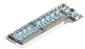
Out of interest, I federating my models together I am very pleased with how well it represents the physical assets, and how the geometry has been kept to a minimum. At the time of writing this post, my Architectural model is just over 12 megabytes (Note: less than 8 megabytes when exported into IFC!); the equivalent of two or three MP3 songs; yet has enough information to represent all of the fixed components within my house.
This slideshow requires JavaScript.
Fantastic, this means that I have now fully populated my architectural, electrical and mechanical models; therefore Plain Language Question PLQ2.4 is now complete!
Model Generation: 2.1 What existing information is available? 2.2 Is there sufficient information to produce a BEP? 2.3 What is the layout of the house? 2.4 What assets are contained within?
2.5 What asset information can be linked to the graphical model?
Now that I have my components, it’s time make sure the right data is included within each of them so let’s see what data is currently being exchanged and work out where the effort is required…
Note: If you have any comments regarding my information model or how I have resolved these issues, then please let me know either on Twitter, or by commenting below.
Hello BIMfans,
Last week’s post where I assembled my light fixture using Mindful Modelling got me thinking about soft landings and the importance of involving others in how information is developed.
No matter who you are, the right support will always help you achieve a softer landing.
What do I mean by soft landings? Well as defined within PAS1192-2, A soft landing requires graduated handover & aftercare based on stakeholder requirements developed from the project outset (Beginning with the end in mind). Doing so allows those who operate an asset to get involved in the design process; impacting on how the asset will meet their operational needs.
The case for soft landings is clear. Have a look at this image below from Constructing Excellence showing different costs that relate to an asset; design and construction actually plays a very small part in an assets life. This is colloquially referred to within industry as the 1:5:200 rule with:
1: Cost of Construction
x5: Cost of Operation
x200: Cost of Business Operations
Now imagine if you could influence the design, to help streamline the operation & business costs? Well, in short that is what soft landings does.
Disclaimer: Diagram may vary depending on success of business
Cookham wood prison is a good example of this. The case study document can be found here. I won’t bore you with the details but in short consultation with prison governors challenged the design to improve the transfer of sound from the wings into the central core, meaning that less staff were needed to monitor the wind; saving a significant amount of money. (If this meant that they could operate with 1 less warden then over 25 years that would be a saving of over half a million!).
Of course seeing the design in 3D was a big help too, turns out that not everyone can read technical drawings.
Soft landings help improve the efficiency of an asset, as a result of this they have been included as part of the UK BIM Level 2 Suite of Standards through the inclusion of BS8536-1; Briefing for Design & Construction. BS8536-1 was developed in line with the principles of soft landings and includes a number of activities and deliverables that could be considered during each work stage; some of which I have incorporated into this project (although as I have no ‘design’ phase, its use is limited).
When developing myPlain Language Questions, I used BS8536-1, and the MoJ Example PLQsto consider what information I wanted to know as the operator and end user of my house. This has led me to ask questions like: “What assets are contained within” so that I know assets require consideration; “3.2 What assets are in a poor condition” and “3.3 What costs can be attributed to my assets” to allow me to draft a planned maintenance schedule; and “3.4 What are the most cost effective thermal improvements that could be undertaken” to allow me to look at the feasibility of some retrofit work.
This mindset has also allowed me to challenge how information is being produced on the project such as creating light fixture assemblies to ensure that I can capture the information I need to manage my assets.
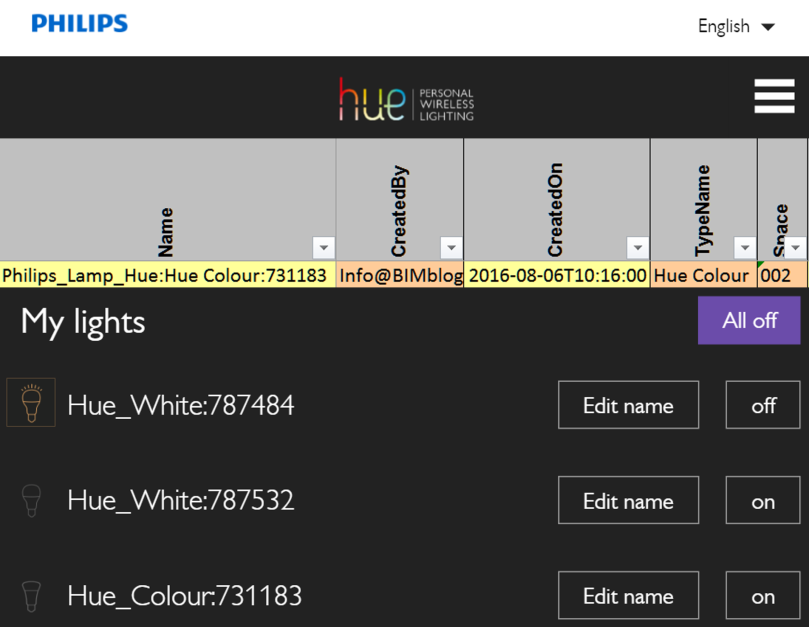
Because of this decision, I have opened up now possibilities on how to use this information. For instance, you may have seen this on twitter last week, but I tweeted an image of my Philips Hue dashboard showing how the names of my objects correspond with what was produced within my information model.
While simplistic my information model has now been connected to a physical object.
And this is really all BIM is trying to achieve. In its simplest form, BIM is:
“Getting the right information: to the right people, at the right time, in the right format” – Me (now)
Soft Landings and BS8536-1 is a core part of this, and has allowed me to put on my operational hat to consider my future needs. Resulting in a model with enhanced information; meaning that when I begin to use this data to operate my house I will be able to hit the ground running thanks to this much softer landing…