Hello BIMfans,
After last week’s population of my Mechanical Model; this week I have populated the assets within my electrical model, but before that a quick update on last week’s COBieissues.
I mentioned last week that no matter what I tried I couldn’t get my classification to exchange correctly. It turns out that I hadn’t defined the classification system in the exporter (oops!), now that I have there are no issues. Guidance on how to do this in Revit can be found using this link from Evolve Consultancy. Note: I still can’t get systems to work, but problem is for another post!
So with that out of the way, let’s talk about mindful modelling; ensuring that you produce your information in a suitable way to satisfy others’ needs.
Much like with inception, the end user needs to be considered for the model to be used effectively; to understand this properly however, we need to go deeper…
How you model can have a BIG impact on the amount of data that can be recorded against an object and depending on what information is needed, it can dictate how something should be modelled. For example take my living room light:
While this may look simple, getting the right data about these objects is tricky.
To start with, if I modelled them as a single object how would I deal with the fact that they have two different manufacturers, the cost of each item is different, and many aspects like their expected service life, colour, material, are different? Also, as I have used a fancy smart bulb, it is the most expensive item here (and therefore the one I care about retaining information on the most). Here is a breakdown:
I know it’s sad, but I’m really impressed with the inner copper colour showing up on the shaded object.
With this in mind I have opted to model each item separately and create an ‘Assembly’. If you are not sure what an Assembly is, it is a method of grouping objects into a schedule-able component made up of a number of individual components, if you will components within components; Component-ception (Sorry!).
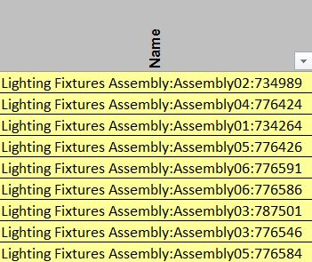
Once set up it allows each Assembly to be recorded when I export my information into COBie, as shown below.
It is still Work in Progress, but the COBie file this came out of can be accessed here.
These items are also broken down into their components too within the ‘Components’ tab. Each of which can be seen below along with the other 48 electrical components within this model. Now that they each have their own row I can collect all of the relevant information I need about each object, so this method has worked perfectly for my needs as the end user.
Of course the downside is I now have three times as many properties to populate…
Note: Due to time constraints (mostly driving to the Brecon Beacons and back!) none of the IFC/COBie properties have been created for these objects, only the minimum information to register them within my COBie ‘Components’ tab for the purposes of answering the currentPlain Language Question.
And there you have it, after considering how I want my data to be exchanged I have created a number of assemblies to allow me to capture the information I need in a form I am comfortable with. At the same time I have also produced my other Electrical objects to that I have a full electrical asset register consisting of lighting, fire detection, sockets, and switches.
As always you can access the work in progress native Revit file, and the exported IFC file
This means that subject to ensuring that the correct property data is attached, I have now fully populated my electrical model; therefore once I have amended my Architectural model Plain Language Question PLQ2.4 will be complete!
Model Generation: 2.1 What existing information is available? 2.2 Is there sufficient information to produce a BEP? 2.3 What is the layout of the house?
2.4 What assets are contained within?
2.5 What asset information can be linked to the graphical model?
Now that I have a pretty strong Electrical & Mechanical model, it’s time to look back at my Architectural model…
Hello BIMfans,
After lasts weeks review of The Importance of being openBIM, this week I have managed to fully populate my mechanical model with all of the assets I want to capture within it to satisfy my Plain Language Question 2.4 (only Architectural and Electrical to go!). The work in progress model can be accessed as both a Native Revit file, an IFC file, and have I even tried to do a COBie export to see where the gaps lie…
Needless to say it hasn’t exactly been a smooth process so far.
While I haven’t given it too much thought, when creating new objects I have tried to ensure that I fill them with the information I need to answer my Plain Language Questions about attribute data; for the most part this has been successful.
Note: So far all I have done is map over the COBie properties and my additional property sets, I haven’t tried to make all my sheets work; that happens during PLQ 2.5.
However, nothing in life comes easy, and COBieis no different. Shown below is a screenshot showing that my components have at least successfully transferred over some of their data with them.
The file is far from complete, but if you want to see how my mechanical COBie file is shaping up, you can access it here.
At this point I have noticed a number of elements work well, and a number of elements work not so well. Note: It is worth pointing out that there is likely to be (an element of) user error as I have not fully investigated how to export this information correctly; yet.
The Good:
Because I have used the shared parameters and property set mapping files I introduced in the last blog post many of my properties are exporting correctly, such as: Bar Code, Serial Number, Material, Shape & Size. I have also managed fixed my dimension error from last week thanks to Autodesk customer support (I had to change the data type from ‘Real’ to ‘Length’). So the attribute mapping process appears to be going well.
The Bad:
I’m afraid that it isn’t all sunshine & rainbows however as some elements are not working exactly as I hoped. Currently: ‘Category’ properties don’t seem to carry despite appearing within the IFC object’s properties, and something similar is also happening with ‘Description’. As you can see below, my IFC file captures this information but when I use xBIM to create COBie the information just doesn’t seem to carry.
Where has that hammer gone?
The Ugly:
It gets worse. As the IFC export doesn’t capture data from linked files I need to create rooms/spaces in each model so that my components can export space information. This means that when I produce my combined COBie file I will need to delete duplicate space instances as I’ll end up with three Living rooms. In addition, no matter what I do I cannot seem to get an object’s ‘Category’ to export and appear within the COBie type sheet (or even other sheets when I tested them too) despite appearing within the IFC. For matters like this I normally turn to xBIM’s Github but sadly I have not found the solution yet.
Finally, within my attribute tab, I am getting duplicate attributes. It appears that despite being recorded as an instance or type property, when exporting some properties are coming out as both; making the sheet more difficult to read and much longer too.
Over the next few weeks as I complete the graphical element of my information model, I will also be looking into resolving these issues to attempt to create a bespoke IFC FM Handover that’ll include as much information to complete my COBie export as possible, and satisfy my data requirements.
But first, let’s focus on the matter at hand. What assets are in my home? Well here is a schedule of all the Mechanical assets I am including that fall under the responsibilities outlined within my Design Responsibility Matrix.
To be honest, at this point I just need to know how many assets I have. I should just be happy that I have 10 objects within my IFC file, and 10 components within COBie too!
And there you have it, now that I have a schedule of my mechanical assets, I am well on my way to answering this Plain Language Question. This means that subject to ensuring I follow suit my Architectural and Electrical information models; completing PLQ2.4 shouldn’t be far away!
Model Generation: 2.1 What existing information is available? 2.2 Is there sufficient information to produce a BEP? 2.3 What is the layout of the house?
2.4 What assets are contained within?
2.5 What asset information can be linked to the graphical model?
Now that Mechanical is sufficiently developed, it’s time to look at some more electrical objects…
Hello BIMfans,
Last week I started to build my mechanical model and had managed to compare different object vendors to select my preferred boiler object. This week I have started to build my electrical model and wanted to discuss the importance of proper data formatting. I need to do so to ensure that when information is exported from my native authoring tool (Revit) into IFC, it is formatted correctly. As an active member of buildingSMART, I am a strong believer in open formats, and the importance of being open(BIM).
What is openBIM you ask? In short, it is the use of non-proprietary methods to delivery asset information. There is a short video that explains it better than I can here.
The non-proprietary method I’m referring to is Industry Foundation Class (IFC); think of it as the PDF of the built environment. No matter what software you use to make a document, if you convert it into a PDF it’ll allow others to access this information without having purchased the software you used; this is what IFC achieves. Note: There any many other benefits too I won’t discuss here, but if you are interested I suggest you read Rob Jackson’s excellent blog post onWhy Use IFC).
As IFC has a language (Schema), it comes with its own grammar (Property Sets) which includes acceptable words (Properties) that can be used providing consistency and the opportunity for validation. For example, take my Nest Thermostat. Under IFC2x3 (the current recommended release) it is classified as an IfcSensorType and I can associate a number of standard property sets to this object to define it. Note: In IFC4 a thermostat is a IfcUnitatryControlType, but for the purposes of this blog I am sticking to the recommended release of 2×3.
To make this a successful BIM Level 2 project, I need to export information about my Thermostat that I defined at the start of blog when I discussed my Model Purposes & Data Requirements. As I discussed during these posts, I will need properties relating to condition, warranty, and manufacturer information. By looking through the IFC Schema I can find suitable property sets and properties to include that are structured in a consistent manner. After searching, I came up with the list below:
Pset_ServiceLife
Pset_EnvironmentImpactIndicators (for my energy use)
Pset_Condition (for monitoring until it requires repair/replacement)
Pset_Warranty (for reference when being repaired/replaced)
Pset_ManufacturerTypeInformation (because it is a manufactured product)
Pset_ManufacturerOccurrence (because it is a manufactured product)
Note: I will also need any properties required for types & components to satisfyCOBiewithin BS1192-4.
The problem is that to do this properly, it take a lot of work.
To help, there is a COBie extension for Revit that helps create COBie files from the native file format (A requirement of PAS1192-2). However, it does not create correctly named IFC properties and each property that is created is prefixed with ‘COBie.<sheet>.<property>‘, I also found it difficult to control which properties did export and which did not. Because of this, I chose not to use the export tool. Also, since I requested IFC as a deliverable within my EIR, I need to make sure that the properties are structured properly; so I have decided to do this the long way.
In order to get a decent looking IFC, I needed to define my property sets. Revit can’t do this. So to do it I had to create a number of shared parameters and a custom property set definition file to allow them to export correctly using the IFC Exporter. At the same time is also used it to define my COBie properties too (excerpt below).
A copy of the defined property set file can be found here.
Using this file, it moves object properties into the defined property sets. This is important because in Revit you cannot create property sets. Because you can’t all the properties end up under one of the pre-defined categories (I’ve chosen IfcParameters for many of them). However this definition file resolves this when exporting.
Shown Left: Properties in the Revit file, Shown Right: Properties in the IFC file, Shown off screen: My agony in getting all of this to work!
Note: To viewIFCfiles there are many viewers available. For this blog I have chosen to usexBIM. xBIM is a free open source viewer that also has the ability to federate models and exportCOBiefiles.
You can access the IFC File for my electrical model here.
Now here is the exciting bit. Because I have defined the property sets I require including all of my Data Requirements and COBie properties I am able to create my COBie data in a number ways including:
Export Revit schedules to transpose into a COBie template;
Install the COBie Extension and remap its properties to use my IFC properties.
So whichever method I choose I have a good set of data I can rely on.
I have 99 problems, but my Thermostat ain’t one.
I will point out however that it isn’t all sunshine and rainbows. There are a few problems that I still need to resolve when exporting into IFC:
I cannot get an object’s category to export properly;
Under my attributes tab, a number of properties have duplicate instances.
UPDATE: I have an issue with my NominalLength and NominalWidth properties, but after contacting Autodesk they have advised me to use ‘Length’ instead of ‘Real’ during the property mapping to achieve this. I have now tested it and it works perfectly, so thank you Angel & Autodesk!
I will continue to explore this and will report back in the future post, but if anymore has any ideas feel free to let me know!
And there you have it, after reviewing how I create my information, I have now developed an openBIM workflow that allows the information I have created in Revit to be exported as an IFC, and this IFC aligned data can be used to create a fully populated* COBie file. Because of this my data is well structured and most importantly consistent with an international schema.
This means that if I apply this process to all of the assets within my model I should then be able to answer this Plain Language Question, and will have all the information I need to have delivered a fully compliant BIM Level 2 Information Model. So let’s get to it!
Model Generation: 2.1 What existing information is available? 2.2 Is there sufficient information to produce a BEP? 2.3 What is the layout of the house?
2.4 What assets are contained within?
2.5 What asset information can be linked to the graphical model?
Now that I have started my electrical model, it’s time to add other assets such as my lights and fire alarms…
Note: If you have any comments or opinions regarding my openBIM process, please let me know either ontwitter, or commenting below.
Hello BIMfans,
After managing to produce my Architectural floor plan drawinglast week, this week I have started to look at my Mechanical graphical model.
Around my home, there are several different heating products I need to register and capture within my information model. So, I thought I would try something different and attempt to use some manufacturer’s objects instead of producing my own. Unfortunately finding suitable objects has proved rather difficult, however, I did manage to find a few boilers on the portals of each of the three most popular online object libraries: National Building Library (NBL), BIM Store, and BIM Object. So I thought I would compare each of them to decide which I would use.
Let the Object Library Wars Commence!
A long time ago, in a graphical model far, far away….
The Rules:
I went onto the portal for each of these online object libraries and searched for the term ‘Boiler’ and selected the closest object available to compare against the requirements within my BIM Execution Plan. These objects were judged by the following categories based on the appropriate BIM Execution PlanspecifiedBS 8541 standards:
BS 8541-1 specifies how to name objects. The name should include three fields separated by an _underscore, written using CamelCase:
Source (The library it was taken from or the manufacturer of the object);
Type (Appropriate IfcType as included in the appendix of BS 8541-1);
Subtype (Additional details NOT covered in the object’s attributes).
For an object name to be compliant I would expect to see something similar to:
WorcesterBosch_Boiler_GreenstarSystems.
So, what names have been used? Shown below are the boiler names as they were downloaded. As you can see each object included a source, however, none of them used the IFC Type or its predefined subtype or product/model name. In addition, both the BIM Store and BIM Object boilers include hyphens which are not permitted.
The NBL boiler is the closest with three fields and CamelCasing, followed by BIM Store which began with the source, and finally, BIM Object last which began with a bespoke category.
Note: I am aware that each of these libraries has their own object standard. However, my EIR didn’t request these. So my BIM Execution Plan needs to comply with the national standards.
Level of Detail:
BS 8541-2 specifies the need to be able to visually represent an object with three levels of detail: Coarse, Medium, and Fine. These levels of detail allow an object to show only relevant elements as required. For example, the detail needed in an assembly drawing would not need to be visible in a general arrangement. I’m pleased to report that each of these objects did incorporate these levels of detail; resulting in a three-way tie.
Source
Levels of Detail Provided
Rank
NBL
Coarse, Medium, and Fine
1st
BIM Store
Coarse, Medium, and Fine
1st
BIM Object
Coarse, Medium, and Fine
1st
Here is the same Boiler at Coarse, Medium, and Fine detail.
Shape and Measure:
BS 8541-3 specifies that product objects (those that represent an actual product) are required to have a coordinating level of detail. This means that the product should be visibly recognizable. However, it also warns about the dangers of excessive geometric detail, which can be seen in these objects. Here are two examples:
Company logo. Shown here is the Worcester logo included in the BIM Store Boiler. Why? The logo itself is only 25mm high and is only legible at quite low scales. What value does having this logo included bring to this object?
As you can see at 1:1 the logo appears fine but becomes unreadable from 1:20
Complex elements. Many of these families utilize nested objects (objects within objects, think Terry Pratchett and turtles). Some of these nested objects are quite complicated for what are essentially graphical placeholders. For example, take the flue basket also shown below from the same BIM Store boiler which uses a horrendous amount of rules to show that it is perforated.
While only being 100mm tall, this flue basket has over 50 (yes, 50!) references to produce the 10x10mm perforations shown.
As you can see below, these additional complexities have negatively affected the file sizes. With NBL again coming out best with the smallest file size by far for their generic boiler.
Source
File Size
Rank
NBL
440KB
1st
BIM Store
1396KB
2nd
BIM Object
2344KB
3rd
NOTE: The file size for the flue basket is 668KB, so this nested object alone takes up more memory than the whole of the NBL Boiler.
Level of Information:
BS 8541-4 specifies that product objects, as defined earlier, should have both specification and assessment attributes. In addition, these attributes should be named in CamelCase and indicate the data type expected. Of the three boilers, only the NBL boiler followed BS 8541-4 fully by using CamelCase throughout its attributes. BIM Store are a close second, follow this convention only for attributes required to achieve BS 1192-4. While the BIM Object boiler does not include BS 1192-4 attributes or use CamelCase.
Spaces, spaces everywhere!
This means that once again the NBLboiler leads with its impressive use of CamelCase, with BIM Store second, and BIM Object third.
However to be frank none of these objects are ideal. For future product objects, it will be much easier for me to create my own. This is due to the limitations I have listed above as well as the fact that these objects cannot be easily configured to suit my needs. For example, for the Classification information to exchange into COBie I require it to be written into a field called ‘ClassificationForObjects’. However, this property doesn’t exist in any of the three boiler objects. In addition, there are a number of attributes I don’t need that will have to be deleted such as the reference to other classification systems, as well as modifications to the geometry to lower the file size.
It has been heavily modified, but you can see the winning NBL boiler in my Mechanical Model.
And there you have it, after comparing three different boilers I have now begun to make the necessary changes to create my final boiler object. This means that subject to ensuring that the correct product information is attached and the inclusion of a few extraction fans, I have now populated my mechanical model; therefore Plain Language Question PLQ2.4 is well underway!
Note: This model does not have any pipework connecting my heating system together, and nor will it. The majority of my pipework is not accessible, and as such, I have decided that I will not guess where they are located. Pipework, therefore, has been excluded from the model until such time as its precise location can be determined.
Model Generation: 2.1 What existing information is available? 2.2 Is there sufficient information to produce a BEP? 2.3 What is the layout of the house?
2.4 What assets are contained within?
2.5 What asset information can be linked to the graphical model?
Now that I have a pretty strong Architectural & Mechanical model, it’s time to look at some electrical objects…
Note: If you have any comments or opinions regarding Object Library Wars, please let me know either ontwitter, or commenting below.
Hello BIMfans,
After starting to author my Architectural graphical model last week. This week I have continued its development resulting in a model which while work in progress is starting to really come together!
As with last week, you can access this model here through Autodesk’s A360 portal.
I was very happy to see that after last week’s blog, a lively debate started on LinkedIn around object naming; as I also had some questions of my own. As you might have saw last week, when I named my walls I did not put the thickness of layers into my subtype. so for example a wall might have been called:
BBH_SolidWall_PlasterBrickwork
I did this because within BS8541-1, table 1 states that the subtype should not capture attribute data. However, while authoring my model I quickly needed to distinguish between walls with the same build up but different thicknesses. Unfortunately, Revit doesn’t allow duplicate family names I couldn’t use ‘BBH_SolidWall_PlasterBrickwork’ for walls with the same layers at different thicknesses, so a solution was required.
BBH_SolidWall_PlasterSingleSkinBrickwork
Initially I described the number of brick skins to avoid recording attribute data within the name, but quickly realised that that was stupid, and I was describing the thickness of the wall, just in a very awkward way. So I was led back to using the thickness of each layer within the subtype.
BBH_SolidWall_15Plaster225Brickwork
Now to make sure my reasoning was sound, I decided to ask Twitter. Interestingly (but not very helpful) the majority of people who participated in my poll thought that both options were wrong.
In fact the correct answer is that ‘both’ are correct. As the wall does not have a predefined subtype, anything goes so long as it has no attribute data, and uses no special characters other than an underscore ( _ ).
To make matters worse, I added some new objects to my model this week that had to use BS8541-1‘s other naming convention for unclassified objects. Basically, if you are using an object without a classification field then the unclassified object naming convention is required, which is a tad more complex:
To use this convention I did what all great men do in times of strife. Ignore the optional fields, in this case it is ‘presentation’. Also why is BS8541-1 now telling me to use hyphens(-) instead of underscores( _ ) between each field in the example object?…
This meant I needed to find out some extra information. We already have my role, in this instance it is Architectural, classification means we need to rely on a Uniclass 2015 table (see example below), we have skillfully skipped presentation, source is my organisation (BBH) as the object creator, type relates to the corresponding IFC type, and subtype will allow me to differentiate between any other similar objects.
Uniclasss 2015: Those underscores will look great inside my kitchen worktop family name…
Meaning that I named my kitchen worktop like this:
A-Pr_40_50_21_45-BBH-Worksurface-Kitchen
Note: Because of the underscore ( _ ) within the classification codes I have used a hyphen (-) as a field separator which doesn’t comply with the text but does comply with the example provided withinBS8541-1. This inconsistency isn’t very helpful, so I have chosen a solution that suits my situation best.
Objects such as kitchen worktops and shelves have been added for a reason. Each of these were needed to accurately reproduce my floor layout, as required to satisfy my next Plain Language Question “What is the Layout of my house?”. So now that they have been modelled, the result is a set of floor plans built into a graphical model that’ll be used for its own purposes as well as capturing what assets I have in order to answer my next Plain Language Question. Once completed I was able to set up suitable views of my floor plans, and transfer them to a title block to complete this deliverable.
And there you have it, after putting in the objects I needed I have now been able to produce a drawing containing my ground and first floor plans which has been derived directly from my graphical model. Using this information I now know the layout of my house; therefore Plain Language Question PLQ2.3 is complete!
Model Generation: 2.1 What existing information is available? 2.2 Is there sufficient information to produce a BEP? 2.3 What is the layout of the house?
2.4 What assets are contained within?
2.5 What asset information can be linked to the graphical model?
Now that I have a pretty strong Architectural model, it’s time to start creating some of my other models to record the electrical and mechanical objects…
Note: If you have any comments or opinions regarding the Layout of my House, please let me know either ontwitter, or commenting below.
Hello BIMfans,
After undertaking a traditional survey of my home last week, this week I have finally opened up a piece of 3D software and started to do some modelling!
First thing’s first; what do I need to actually produce? Well, after reviewing my Master Information Delivery Plan (MIDP), and the responsibility matrix within my BIM Execution Plan (BEP), I need to produce an Architectural Model which includes: External walls, internal walls, door, windows, roof, floors, fascia, gutting and anything else associated with the external structure or internal layout. So to do this I need some objects, but it isn’t as simple as that..
First, I need to either find the right objects, or build them myself. Now this week I have managed to build my own (so I won’t discuss online object libraries this week) but once I had built my objects I found that picking their names was a challenge!
Few people have ever had to name a wall!
Now luckily for me to make sure that good consistent naming was used I specified within my Employer’s Information Requirements (EIR) that BS8541-1should be complied with; the British Standard for object identification. Within this standard it states that objects using the software’s associated classification (Like when you use a Wall object to represent a Walls) should use three fields.
Source:
Source is easy, I made these objects so I have used the the same organisation code I used in my EIR & BEP; BBH (BIMblog.house). However if they are downloaded from another source, then they should be identified as the source.
Type:
Type are also fairly easy as BS8541-1suggests the use of the corresponding IfcType which can also be found on the IFC Schema page.
Subtype:
Subtype has little guidance but states that this information should not captured within the attribute data, so with that limitation I have used this field to describe the structure of my objects. For example, a partition wall object has the subtype ‘PlasterStudPlaster’, so describe the layers used within.
Note: All fields need to use CamelCase (no spaces) and special characters are not permitted either!
Annoyingly many of the standard objects within the software package I was using (Revit) didn’t strictly comply as hyphens ‘-‘ are only permitted in objects without associated classifications. So, after creating a number of my own objects, I ended up with a list like this:
Note the BS8541-1 non-compliant default families that I couldn’t purge at the bottom of the list.
Now that I have a consistent naming method, it’ll be easier to identify these objects when they appear in schedules and eventually within my COBie export. So, to the modelling!
Those of you who follow me on Twitter, may have seen my frustration at modelling my home last night. As my home is a 1900s Victorian Terrace, it isn’t exactly built perfectly straight. In fact, when I tried to use a photograph to check my dimensions by course counting I discovered something very interesting; my courses don’t add up!
What kind of unholy monster would do this???
So sticking to my internal dimensions, and modifying some of my wall thickness to take into account imperial brick dimensions, I have started to create my graphical model. Currently Work in Progress, this model currently includes:
Generic floor objects with a depth based on my landing void;
Wall objects based on my survey measurements, and has started to be populated with bathstone detailing and render on the rear facade; and
Generic roof objects based on pure conjecture (to be revised!)
You can access a copy of this Work in Progress 3D Model here to interact with through Autodesk’s A360 portal.
There you have it, after some frustration trying to make my measurements add up, this model is now starting to look like my home. However, this model isn’t complete by a long shot, so I hopefully by next week it’ll have sufficient content so that I can answer my currentPlain Language Question, PLQ2.3.
Model Generation: 2.1 What existing information is available? 2.2 Is there sufficient information to produce a BEP?
2.3 What is the layout of the house?
2.4 What assets are contained within?
2.5 What asset information can be linked to the graphical model?
Now that I have started this model, it’s time to add some further objects, to answer PLQ2.3…
Hello BIMfans,
Now that I have checked my Data Security requirements, I am able to move into production of information. It has taken 17 blog posts (17? Doesn’t time fly!) but I have finally opened some CAD software to start producing some information about my home. Wooohooo!
Now originally I had arranged for a friend with a point cloud scanner to come by and measure my house. If this had happened it would have had a sexy point cloud file I could have shared with you. However, their timing didn’t work out. Luckily for me however, I still have a Disto & tape so it was time to roll up my sleeve and do some old fashioned surveying!
Sadly, Lizzie had better things to do than to help me Survey my home….
So to start lets refer to my TIDP, I need to produce a Survey that can be used as a precursor to produce my 3D graphical models. Also, by referring to my BEP I needed to:
File Name & Format:
This one is simple as I have a convention outlined that I need to follow compliant with BS1192. However, while surveying I decided that it was easier to keep both floors in separate files so that I can use the correct origin points and not worry about overlaying lines with different offsets. Because of this, I have now revised by TIDP to reflect two separate survey files and made sure that the uploaded files are DXF as specified within my BIM Execution Plan:
Layer Naming:
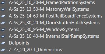
This one was also pretty simple as I have opted to also follow the BS1192 container naming for my AutoCAD layers. Using NBS‘ Uniclass 2015 search tool, I identified the appropriate system classifications for the layers I needed to survey my: Walls, Doors, Stairs, & Windows and dimensions. Note: Please ignore the bright colours in the CAD files, they are a visual aid more than anything else.
If I had £1 every time I had to write an underscore.. (Thank you Dan Heselwood for spotting a typo)
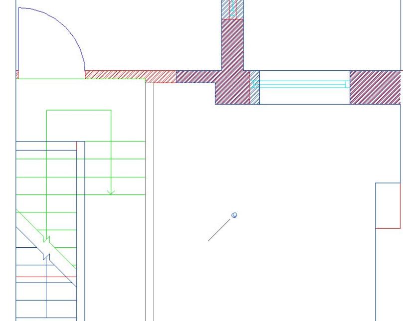
Symbology:
Referring to my copy of BS8541-2, I made sure that any symbols I used were included within. In this file I had a number of symbols which included: Architectural ticks for dimensions, and 2 ceiling height symbols (one for ceiling height, and one relative to FFL). In addition, I also needed to use symbols to represent doors, windows, stairs and walls; all of which are included within BS8541-2, even the brick hatch that I used is specified within. Using clear symbology based on an agreed standard when drafting is key, as without a clear message on drawings, disaster can occur.
Typically this is not how Architects revisions are resolved on site…
Origin Point & Tolerances:
Finally, by following the origin point I had set out in by BIM Execution Plan, I was able to ensure that my files align providing a coordinated set of survey data. In fact to make sure that my survey’s aligned I imported both of them into Revit to compare. UnSurprisingly, both files closely aligned, after taking a few extra check dimensions and then resigning to the fact that buildings are not straight. I tweaked a few final dimensions within tolerance and ended up with two coordinated survey files that line up perfectly when imported based on their origin points.
It is as if I planned for this to happen
There you have it, by planning how I need to undertake the work, I was able to efficiently produce coordinated survey data in a usable format, ready to be used to produce my 3D graphical models. However, as I haven’t produced floor plan PDF deliverable, so I won’t call this Plain Language Question complete just yet:
Model Generation: 2.1 What existing information is available? 2.2 Is there sufficient information to produce a BEP?
2.3 What is the layout of the house?
2.4 What assets are contained within?
2.5 What asset information can be linked to the graphical model?
Now that I have my 2D survey data, it’s time to finally do some 3D modelling…
Note: If you have any comments or opinions regarding my survey files, please let me know either ontwitter, or commenting below.
Hello BIMfans,
After Validating my BIM Execution Plan last week, the next step is for me to start to producing information about my home. However, before I do so, I wanted to go over my data security requirements to make sure I haven’t missed anything, and that my data is safe to share on this blog.
Secure, for my pleasure.
Right, first thing’s first; If anyone is doing BIM and concerned about data security then the first document to consider should be PAS 1192-5. Note: I am personally not a fan of this document but that is another topic for another blog.
The goal of PAS 1192-5 is admirable, it intends to :
Protect information about the location of sensitive assets;
Protect information about assets that are considered sensitive; and
Recognize where data collection could compromise the security of an asset.
Perfect, I do not want everyone reading this blog to know where I live or know any details about my home that may make it a target, so PAS 1192-5 seems perfect.
However, once I had read PAS 1192-5, it quickly stops being relevant as my home does not form part of the national infrastructure and is not yet a landmark; therefore is not considered a ‘sensitive asset’, meaning that the PAS 1192-5does not apply. Instead, it suggests that I meet base security requirements as well as the Governments Cyber Essential Scheme and the Security Policy Framework. However, the Governments Cyber Essential Scheme is not applicable as I have outsourced responsibility for my network to Google (thanks Google!) through hosting my files on Google Drive, and the Security Policy Framework is very high level and relates specifically do HMG data, of which I am collecting none.
So what next?
Thinking about it, my concern is not with Data Security but more do to with handling personal information. While I am happy for you to know lots about me, without my wife’s consent if I were to advertise our address and contents of our home there would certainly be an issue around data protection and personal safety (my personal safety!). So, I instead referred to information from the International Commissioner’s Office (ICO), who have several useful resources relating to the Data Protection Act. Which calls for me to assess:
What information do I intend to share? The graphical models, non-graphical data, and documentation I will be producing about my home.
What is the objective of sharing this information? To demonstrate how BIM Level 2 processes can be successfully applied to a small-scale residential scheme in a pragmatic and straightforward manner.
How do I intend to share it? Place information within a Google Drive folder with public access.
What risk does sharing the data pose? Provide unintended personal or sensitive information about occupant(s) and their home. “Oh look, Dan’s TV is right next to this window..“. Note: It is worth mentioning that information, such as contact details and addresses, can appear in many locations. Prior to the release of this post, my address could be found using a website identity service likewhois.net (until this week when I paid to have this information hidden).
Could the objective be achieved through anonymising it? Yes as the information doesn’t need to be complete, just consistent. However, there is a time resource related to the manipulation of any information, therefore, the preferred method is to exclude sensitive deliverables for sharing.
Will data be transferred out of Europe? I don’t know.
The Data Protection Act has strict rules around having personal information leave Europe#DataBrexit. Google have several data centres across the globe so any personal information could be transferred to any of these. However, Google have established sufficient contract clauses to comply with the Data Protection Actand use their data stores outside of Europe. To avoid this problem, I should avoid the inclusion of any personal or sensitive data within my shared deliverables. Much like traditional risk assessments, the best solution is to follow ERIC (Eliminate, Reduce, Isolate, Control).
You will respect my data security authoritah!
Luckily I have already been eliminating personal information from my documentation though removing addresses, as well as reducing the risk through supplementing real-world coordinates for a 0,0,0 project base point in my BIM Execution Plan. Therefore, by controlling the remaining data within my models through removing any physical location information, I should not be sharing any personal or sensitive information.
And there you have it, by carefully considering my information requirements through using the (somewhat) relevant Standards, I have further enhanced by data security plan; fantastic. This means that I am ready to start producing information to answer my next Plain Language Question, PLQ 2.3
Model Generation: 2.1 What existing information is available? 2.2 Is there sufficient information to produce a BEP?
2.3 What is the layout of the house?
2.4 What assets are contained within?
2.5 What asset information can be linked to the graphical model?
Now that I have properly considered data security, it’s time to produce some information and work out the Layout of my home…
Note: If you have any comments regarding my data security conclusions, then please let me know either on Twitter, or by commenting below.
Hello BIMfans,
Following the publication of my Draft BEP a fortnight ago, I decided that I needed feedback to ensure that what I have written is suitable (as I did with my EIR). Having worked on both the client and supply side in the past I am confident in my work, but it is always good to get some fresh perspectives. As such I asked a few friends in the know.
Meet Athos, Porthos, Aramis, and D’artagan who kindly offered to help with my Review
I asked each of them to review my BEP as if I was procuring their services, as well as asking for any suggestions for improvement. Here is what they had to say:
Kier Group are a leading property, residential, construction, and services group with offices across the globe whose core principles are set around collaboration, forward thinking & enthusiasm. Andy is also a BRE BIM Level 2 Certificated Professional.
“Dan’s post-contract BEP is very well prepared – clear, concise and fully compliant to the suggested requirements set out in PAS 1192-2. The content is light in places however this is clarified and acknowledged due to the nature of the project – a residential house development where Dan is fulfilling/simulating all stakeholders. I would have liked to have seen a diagram of the ‘high level’ CDE in lieu of a process and data management platform, and a little more detail for fictitious subcontractors that may contribute to the PIM. Certainly if more ‘BIM professionals’ in the industry refer to this example as a template to structure against, we would all see better BIM Execution Plans to a consistent standard.” 9/10
HLM Architects are a UK wide Architecture design group with a strong ‘one team policy’ based around the pillars of their: Client, People, and Quality. HLM have also been recognised having achieved BRE BIM Level 2 Business Systems Certification.
“Dan’s BEP is an interesting read as it gives good guidance on completing all sections of the post contract-award BEP. A very good example of how to apply the BEP to small size projects and breaks the myth that BIM is for big projects only; I see that as the biggest strength of the blog and is highly commendable. However, as a naïve reader one aspect that may come across confusing is the involvement of fictitious task teams. ADR, MDR, KDR and EDR were used as part of the MIDP whereas other sections state that CDE and supplier assessments are not required as Dan is client, designer and operator.” 7/10
Imtech are one of the largest independently owned and managed technical service providers in the UK and Ireland, with extensive expertise and experience in engineering services, technical facilities management, and systems integration.
“Dan’s post contract-award BEP is an excellent example of how you apply and make relevant the standards within a BIM execution plan. Ensuring that they cross reference one another throughout the document provides better clarity of purpose for the suite of BIM documentation to be used on a project. If Imtech were to respond to the BEP I would be seeking clarification on methodologies of information transfer and model review and validation. This is best displayed graphically from experience and would have consolidated the the well tabulated information provided within this BEP. For this reason, for me, it’s not a perfect ten but a pretty close” 8.5/10
All-in-all pretty positive, although there is room for improvement. Following these reviews, I have revised my post contract-award BEP considering two key areas in particular: The fictitious roles, and transfer of information:
Fictitious roles.
As Paul & Meenakshi point out, this section is not very clear and seems to conflict with other areas of the post contract-award BEP, Andy also wanted more information, so there is clearly something lacking.
Note: The plan was to invent a few roles because I am an army of one so that I could produce an MIDP; showing a clear way to manage responsibility. However, as it is just me, it makes how I authorize and exchange information much more difficult (and the fact I don’t manage a CDE). I cannot think of a clean way to resolve this while maintaining my MIDP until another organization contributes to the project, so it will remain as it is for now.
To make this section clearer short term, I have replaced ADR, MDR, EDR etc with Arch1, Mech1, Elect1, updated my MIDP to suit and have revised the text within the BEP to clarify around the relationship of these roles.
Exchange of Information.
As Dwight pointed out there is little information included around the exchange of information which is also something Paul had also mentioned too. Therefore, I have clarified the purpose of the scheduled software within my BEP and included the exchange of information into a high-level diagram to also satisfies Andy’s queries around clarifying Data Management.
Finally, in response to the feedback, I have:
Updated by origin and orientation section so that my project base point is the lowest and most left point (ie no negative values),
clarified the purpose of the software I am using, and
corrected a few typo’s which I had not caught within the BEP.
It feels much more complete and robust now, so thank you Andy, Paul, Meenakshi & Dwight.
And there you have it, by gaining some much needed insight from the industry I have now improved my BEP and gotten it validated too, fantastic. This means that I have now answered my BIM Execution Plan Plain Language Question; PLQ2.2 Complete!
Model Generation: 2.1 What existing information is available? 2.2 Is there sufficient information to produce a BEP?
2.3 What is the layout of the house?
2.4 What assets are contained within?
2.5 What asset information can be linked to the graphical model?
Now that I have my finalised BEP it’s time to start producing some information, but first let’s make sure I have sufficiently considered my Data Security…
Note: If you have any comments or opinions regarding my BIM Execution Plan, please let me know either on Twitter, or commenting below.
Hello BIMfans,
Before I consider last week’s BIM Execution Plan complete, I need to finish an outstanding item within my appendix; my Master Information Delivery Plan (MIDP).
Primary plan for when project information is to be prepared, by whom and using what protocols and procedures, incorporating all relevant task information delivery plans (TIDPs).
So (in plain language) a MIDP is a programme that includes all of the documents that will be produced on a project, and who will be producing them.
To make a MIDP I’ll need to first create some Task Information Delivery Plans, a schedule of documents to be produced by each team. If you want to know about TIDPs, there is a great post on them by Rob Jackson of Bond Bryan Digital; but for now, it’s project management time!
Project Manager: Someone who believes that nine women can deliver a baby in one month – (He may be familiar to those of you who read Dilbert)
Using last week’s BIM Execution Plan, I have broken down the work on this project into three task teams (all being done by me!):
Architectural,
Electrical, and
Mechanical.
Each team was given the MS Excel template I made to list all the documents that they will be producing for my house. Luckily for me, this project is simple, so the only documents being produced by my Electrical and Mechanical teams are their graphical models. However, the Architectural team will also be producing drawings, COBie, and some schedules. For ease of reading, I have put all of the TIDPs into a single spreadsheet that can be accessed here.
You’ll hopefully notice a few clever tricks I have used. Firstly, I have aligned the column headings to column names within MS Projects so that I can import my TIDPs easily. Secondly, I have used the Concatenate function within MS Excelto pull each of the file naming fields into a single field to improve readability while maintaining control through a pick list. Once filled in, I was able to import into Projects, set up the preceding files to form my critical path, and included key review dates to create my Master Information Delivery Plan.
Now that I have my MIDP, I can use this plan to manage what files are produced when and by whom. This is done two ways:
The dates generated in Projects were exported out, and then inputted back into each TIDP so that each can manage their resources using their own document, and
I can now refer to the MIDP to make sure that each week all teams have completed the files needed so that all task teams have the information they need, when they need it.
There you have it, Master Information Delivery Plan complete! I can now manage all the files being produced for my house, my BIMExecution Plan has also now been revised to include the MIDP within the appendix. As I still haven’t had my BEPs reviewed, I will continue to not consider this Plain Language Question complete.
Model Generation: 2.1 What existing information is available?
2.2 Is there sufficient information to produce a BEP?
2.3 What is the layout of the house?
2.4 What assets are contained within?
2.5 What asset information can be linked to the graphical model?